AC-JTAG 1149.6 and 1149.1 (JTAG) Interconnect Shorts/Opens Tests
The Intellitech Virtual Interconnect Test
(VIT) package is a comprehensive automatic test generation and diagnostic solution for
developing high fault coverage tests for IEEE 1149.1
and 1149.6 based systems. 1149.6 (AC-JTAG) is the add-on standard to 1149.1 which describes nets which include DC blocking capacitors either on the PCB or within the IC receiver*.
|
Intellitech's pattern generator automatically creates test
patterns for interconnect wires between boundary-scan devices
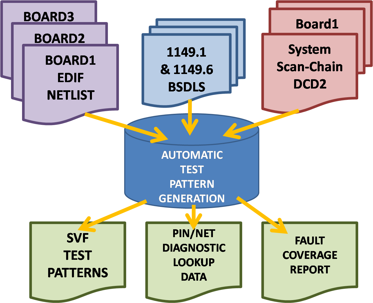
with single-ended and differential drivers/receivers. The interconnect may be present on a single PCB or the interconnect may be between multiple PCBs in a system. The ATPG (Automatic Test Pattern Generation Tool) supports heirarchy, enabling interconnect tests of mezzaninne cards and daughter boards to motherboards. The pattern generator analyzes the system level topology, BSDL files and then generates test patterns, diagnostic data and a fault coverage report. |
 |
AC-JTAG 1149.6 and JTAG/1149.1 Interconnect Overview
The EDIF netlists from industry standard CAD systems defines the PCBs connectivity and the pin properties of all the devices in the design. This information enables robust interconnect test generation when non-1149.1/1149.6 devices are present. This information also enables the generation of netlist-based constraint checking that is essential for preventing inadvertent damage to devices during debug as well as extracting information about the non-1149.x devices present in the design. IEEE BSDL models for each 1149.1/1149.6 device describe the boundary-scan architecture for each device. The device chain description files (DCD2) defines the scan chains(s) order for the system including complex scan-ring-linking devices that assist with routing system level scan rings.
The Virtual Interconnect Test engine automatically creates test vectors for all the 1149.1 and 1149.6 based PCB defect types. These include, stuck-at ('1', '0'), opens and shorts on both differential pairs such as LVDS and single-ended I/O such as LVTTL/LVCMOS. VIT automatically handles complex high-speed point-to-point differential signal termination resistors and on-chip AC coupling caps. These types of nets are found in today's Xilinx Virtex-5, Virtex-6 and Altera's Stratix IV and Stratix 5 FPGAs. Intellitech's VIT also generates special tests to catch shorts on FPGAs with 2.5V or lower voltage I/O that other ATPG tools miss.
VIT generates tests vectors, for scan and non-scan devices, and writes the test data out in industry standard Serial Vector Format (SVF). SVF describes Instruction and Data Register scan operations without the detailed TAP state transitions. VIT generates a fault coverage report and diagnostic look-up tables. The report lists the fault coverage in terms of a percentage and catalogs the detected and undetected faults by name.
VIT
produces diagnostic support data in one of two formats. The most advanced format is the expect data file. This option describes the expected behavior of a good board during the virtual interconnect test and is used by the advanced BSID diagnostic engine. Optionally, there is a more detailed level of diagnostics available called Boundary Scan Intelligent Diagnostics (BSID). The BSID engine performs analysis that is more exhaustive; reports fault information to the pin and net level and identifies the type of fault that may be occurring -- short, stuck-at, or opens.
By default, VIT produces a dimplier optimized diagnostic lookup table. This is an ASCII file that lists which net is faulty for all possible types of failures that could occur during the virtual interconnect test.
SVF data is applied to the Unit Under Test by Eclipse. Schematic Logic ProbeTM (SLPTM) and Virtual Fault AnalyzerTM (VFATM) are used to help isolate PCB failures. These tools are available with the Eclipse Test Development System and the Eclipse Scan Executive Test Station.
We had boards that had ‘passed’ ICT and boundary-scan tests at the CM, but were non-functional. Intellitech’s innovative multi-processor fault coverage covered interconnects missed by the CM’s tests. Joe Gagnier, Manager, Unisys Read More about Interconnect Tests
AC-JTAG 1149.6 - JTAG 1149.1 Interconnect Test Features
- 1149.1 Interconnect Testing
- 1149.6 AC-JTAG AC Coupled Nets interconnect testing
- Intellitech exclusive low-voltage driver-off marching 1s test for <2.5V nets
- Robust fault model support including:
stuck-at ('1', '0'), opens and shorts and point-to-point differential signals (series and termination resistors are tested)
- Support for hierarchical netlists and multi-PCB systems without 'netlist merging'
- Optionally, constrain pins to accommodate special design cases
- Fast Fault Diagnosis with PinFault diagnostic engine
- Enhanced diagnosis and isolation for shorted vias with
SLP and VFA
- Optional MCM and multi-board support without netlist
modification using CircuitMergeTM
*High-speed serial links typically are AC - coupled however, the 1149.6 standard only provides a method of testing for stuck-at faults - no high-speed testing is enabled via the 1149.6 standard. At-speed testing of these nets is done with Intellitech's BERT-IP instrument for FPGAs. |